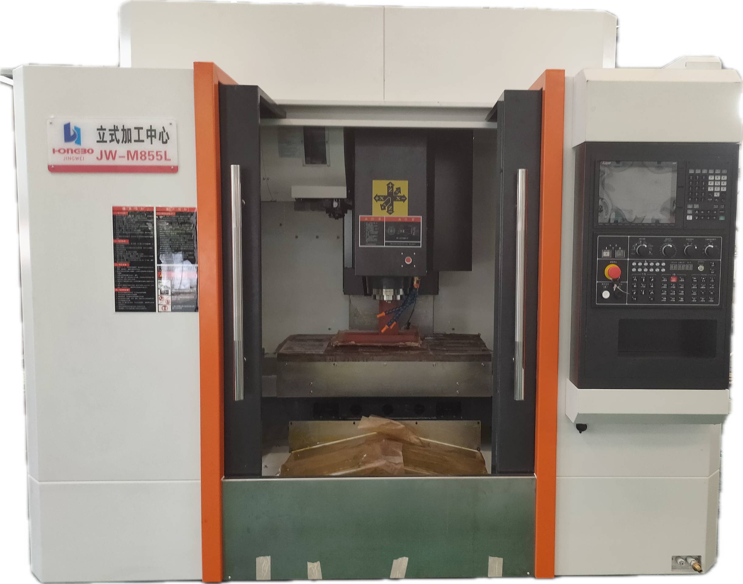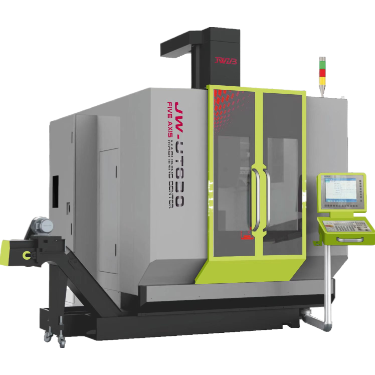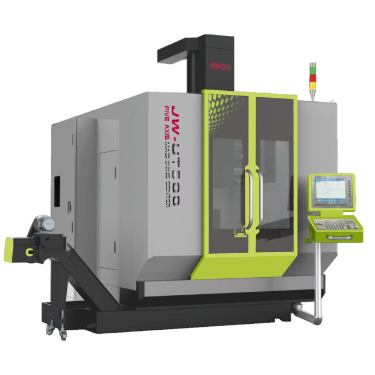
Main technical description of JW-UT350 five-axis machining center
The JW-UT350 five-axis machining center adopts a bridge-type gantry structure, and the XYZ axes use 45 roller linear guides. It is composed of an AC-axis cradle turntable, bed, saddle, ram, high-speed electric spindle, hydraulic system and other parts, and is equipped with an automatic chip removal device and a tool magazine. This processing center can perform milling, drilling, reaming, boring, tapping, 锪 and other processing procedures on parts. It is suitable for processing complex two-dimensional and three-dimensional concave and convex molds as well as complex cavities and surfaces. It is widely applied in industries such as aviation, aerospace, automobiles, molds, heavy machinery, locomotives, shipbuilding, mechanical and electrical, machine tools, printing, light textile, and medical devices.
- Machine Tool Characteristics
1.The machine tool adopts an integral gantry structure, with the ram installed on the cross beam to achieve X-axis movement. The crossbeam is installed on the bed.
Achieve Y-direction movement; The spindle box is installed on the slide seat to achieve the up and down movement of the Z-axis. The turntable is supported and force-bearing at both ends. The main force-bearing end is supported on the base, and the tailstock is supported on the base to achieve the swing of the A-axis. The workbench is installed on the bridge frame to achieve the rotational movement of the C-axis. The two rotating axes A and C drive the workpiece to move, while the X,Y, and Z axes drive the tool to move.
2.The main components of a machine tool consist of the bed, crossbeam, slide, headstock and cradle turntable. The material properties endow the machine tool with excellent static precision stability, dynamic performance and long-term thermal stability. The design of the bed body has undergone finite element analysis. Its structure is reasonable and the rib plate arrangement is appropriate, thus having sufficient static and dynamic stiffness as well as precision retention. The base, crossbeam, slide seat, main shaft box, turntable cavity, etc. are all made of high-strength cast iron and cast by resin sand process. They have a complete heat treatment process to eliminate residual stress, and sufficient reinforcing ribs are arranged. The best structure is obtained through finite element analysis to ensure that the whole machine has sufficient strength, rigidity and high stability.
3.The X/Y/Z axes adopt linear roller guides, featuring high rigidity, low noise and low friction. They can perform rapid displacement and achieve the best circular accuracy. The X, Y, and Z axes are directly connected by AC servo motors through couplings, featuring strong rigidity, flexible and easy movement, and driving the ball screw for stepless transmission. The AC servo feed motor serves as the power source, and the ball screw acts as the transmission part Ensure the feed accuracy of the lead screw. The Y-axis is driven by a servo motor. Under the premise of effectively controlling the drive yaw, the drive speed and rigidity of the Y-axis are maximized. The Z-axis servo motor is equipped with an automatic brake function. In the event of a power failure, it can automatically actuate the brake to hold the motor shaft tightly, preventing it from rotating and providing safety protection.
4.The main shaft is a high-speed and high-precision mechanical main shaft, and the corresponding tool holder is the HSK-A63 type tool holder. The standard maximum rotational speed is 20,000 RPM. The spindle can achieve stepless speed regulation within its speed range. The spindle is controlled by an encoder built into the motor, which can realize the functions of spindle orientation and rigid tapping.
5. The rotary table surface, also known as the worktable, has a diameter of 400mm. The turntable adopts high-quality direct drive torque motors without intermediate transmission links, achieving rapid, efficient and accurate motion control. Pneumatic automatic clamping ensures accurate and reliable movement. Axis A is the swing axis, with a swing Angle of ±120. The C-axis is the rotation axis and can rotate 360 degrees. Rotate freely.
6.The tool magazine is a horizontal chain-type servo tool magazine with a capacity of 24 tools and automatic tool changing. The maximum tool diameter is φ 75mm and the maximum tool length is 300mm.
7.Lubrication system :The feed section is equipped with an electric lubrication pump and a quantitative oil injector to precisely and quantitatively inject lubricating oil into the lubrication points of the sliding guide rails and ball screw pairs, ensuring the long-term stable operation of the machine tool. A centralized lubrication method is adopted.
8.Chip removal system:The iron chips produced during the processing directly fall onto the protective wall. The inner inclined protective wall enables the iron chips to slide smoothly into the chip removal trough, and then the iron chips are conveyed to the chip receiving trolley through the chain plate chip conveyor. It is simple, practical and economical.
9.Machine tool protection:The machine tool is equipped with a fully enclosed protective room, which is convenient and safe to operate. The X, Y and Z axes are all equipped with protective covers, effectively preventing iron filings from eroding the guide rails, protecting the guide rails and lead screws, and extending their service life.
10.Detection device:The detection components of the A/C axes of the machine tool are all standardly equipped with grating rulers (XYZ can be optionally equipped with grating rulers), which can achieve high positioning accuracy and high stability. The machine tool is standard-equipped with a tool setting instrument to achieve tool setting within the machine and improve processing accuracy.
Ii. Main Configurations of JW-UT350 Five-axis Machining Center
(1):Host: JW-UT350
(2):Spindle: HSK-A63 15000 RPM spindle, power 30KW, torque 69.4NM
(3):Feed axis: The XYZ axes are directly driven by servo motors and ball screws, and are equipped with grating rulers to form a full closed-loop system. The AC shaft is driven by a DD motor. Z-axis motor with brake. The AC shaft adopts oil cooling, which facilitates the timely dissipation of heat.
(4):Tool magazine: 40-position tool magazine
(5):Cooling system: Standard cooling system
(6):Hand-cranked: External hand-cranked
(7):Chip removal system: Chain chip conveyor.
(8)Chip flushing system: Standard chip flushing system
(9):Lubrication system: Standard lubrication system
(10):Protection: Standard protection
(11):Workbench: The diameter of the disk surface is 400 mm
(12):System:SYNTEC Systems
Main function: Equipped with a 15 “display,
Five-axis linkage function(RTCP)
Programming in right-angle and polar coordinates, absolute and incremental dimensions.
Programmable coordinate translation and rotation
Basic interpolation methods such as linear, circular arc, and helical, circular arc interpolation, and NURBS interpolation.
The tool parameters can be programmed and modified.
The control system is equipped with functions such as rigid tapping, basic mathematical function calculation, logical operation, mirroring, nesting of subroutines at level 4 or above, tool life monitoring, and automatic diagnosis of various software and hardware faults. It also has fixed processing cycle functions for basic processing methods such as milling, drilling and boring, tapping, and reaming. Moreover, it has compensation functions for pitch error, clearance, and backlash. It is equipped with the function of directly extracting and replaying processing programs from the equipment controller and peripheral servers, supports cutting speed control commands, has anti-collision protection devices for each drive shaft, and has a simulation system for testing processing graphics and tool path graphics
(13):Calibration system: Calibration ball +3d probe
(14):Tool setting system: Contact tool setting, measuring tool length
( 15):Working conditions of machine tools
Power supply: 380V±10%, 50HZ±1%, three-phase alternating current
Ambient temperature: 25℃-30℃
Relative humidity: 40-75%
III. Main technical parameters of JW-UT350 five-axis machining center
| Machining center model | JW-UT350 | |||
|
Three-axis travel |
X-axis travel | mm | 500 | |
| Y-axis travel | mm | 500 | ||
| Z-axis travel | mm | 450 | ||
| A-axis stroke | -120~+120 | |||
| C-axis travel | -360~+360 | |||
| From the end face of the main shaft to the turntable surface (0°) The distance | mm | 100-550 | ||
|
Workbench |
Workbench diameter | mm | 350 | |
| The maximum rotational diameter of the worktable | mm | 530 | ||
| Maximum height of the workpiece | mm | 400 | ||
| Workbench load-bearing capacity (horizontal/inclined | Kg | 250 | ||
| The maximum distance from the A-axis -90 to the center of the spindle | mm | 305 | ||
| The maximum rotational speed of the A/C axis | rpm | 90/60 | ||
| A-axis torque (rated/maximum N.m) | 1290/2400 | Dual DD direct drive | ||
| C-axis torque (rated/maximum N.m) | 600/1100 | Dual DD direct drive | ||
|
Main axis |
Main shaft specification | HSK-A63 | ||
| Spindle diameter | mm | ¢150 | ||
| Spindle diameter | rpm | 20000 | ||
| Power (S1/S6) | Kw | 20KW | ||
| Torque (S1/S6)(40%) | Nm | 35/42NM | ||
|
Three-axis motor |
X-axis servo motor | Kw | 3.9 | |
| Y-axis servo motor | Kw | 5.9 | ||
| Z-axis servo motor | Kw | 5.9 | ||
|
Lead screw Guide rail |
Specifications of X-axis guide rails | Roller | 35# | |
| Y-axis guide rail specifications | Roller | 35# | ||
| Z-axis guide rail specifications | Roller | 35# | ||
| Specifications of X-axis ball screw | mm | 4012 | ||
| Specification of Y-axis ball screw | mm | 4012 | ||
| Z-axis ball screw specification | mm | 4012 | ||
|
Feed |
Rapid displacement | m/min | 36 | |
| XYZ Cutting displacement speed | mm/min | 1-10000 | ||
| AC Cutting displacement speed | mm/min | 60/ 100 | ||
|
Tool magazine |
Type of tool holder | HSK-A63 | ||
| The number of cutting tools | set | 24 | ||
| Maximum knife length | mm | 300 | ||
| Maximum diameter of the knife | Full knife | mm | 75 | |
| Adjacent hollow knife | mm | 120 | ||
| Tool weight | kg | 8 | ||
| Tool changing form | Choose a knife nearby | |||
| Tool change time | sec | 1.8 | ||
|
Power source |
Machine tool voltage/frequency | V/Hz | 380/50 | |
| Total electrical capacity | KVA | 52 | ||
| Gas source pressure | mpa | 0.5-0.6 | ||
| Gas source flow rate | ml/min | 350 | ||
| Precision | XYZ axis positioning accuracy | mm | 0.006 | |
| AC axis positioning accuracy | ″ | 5 | ||
| Repeatability accuracy of the XYZ axes | mm | 0.004 | ||
| Repeatability accuracy of the AC axis | ″ | 5 | ||
| Machine dimensions and weight | Height | mm | 3000 | |
| Land area | mm | 3200X2000 | ||
| Net weight (approximately) | kg | 7000 | ||
Ⅳ.List of Main Purchased Parts for JW-UT350 Five-Axis Machining Center
| Serial number | Name | Quantity | Remarks |
| 1 | Instruction Manual of Numerical Control System | One copy | |
| 2 | Machine Tool User Manual (Mechanical Part, Electrical Part) | One copy | |
| 3 | Factory Certificate of Conformity | One copy | |
| 4 | Packing list | One copy | |
| 5 | Tool Magazine Instruction Manual | One copy | |
| 6 | Anchor bolts | 1 set | |
| 7 | Floor MATS | 1 set | |
| 8 | Toolbox | 1 set | |
| 9 | -shaped spiral knife | 1 piece | |
| 10 | Cross-helical knife | 1 piece | |
| 11 | Allen wrench | 1 set | |
| 12 | Handheld remote control unit | 1 piece | Remove from the machine tool |
| 13 | AC Shaft Instruction Manual | One copy | |
| 14 | Spindle Instruction Manual | One copy | |
| 15 | Instruction Manual for CNC Rotary Table | One copy | |
| 16 | Water-cooled machine Instruction manual | One copy | |
| 17 | Hydraulic Station Instruction Manual | One copy | |
| 18 | Air gun | 1 piece | |
| 19 | Water gun | 1 piece |
| 1 | Host | JW-UT350 | Tai zheng | 1 unit | |
| 2 | Protection | Honwon | 1 set | ||
| 3 | Numerical control system | SYNTEC | SYNTEC | 1 set | |
| 4 | Tool magazine | HSK-A63-40T | Fang Guan | 1 set | |
| 5 | Cooling of the electrical cabinet | Leide | 1 piece | ||
| 6 | Spindle cooler | Leide | 1 piece | ||
| 7 | Lead screw | 45# roller | THK | 1 set | |
| 8 | Guide rail | 4012/5012/4012 | THK | 1 set | |
| 9 | Water pump | 750W | Weisen | 1 piece | |
| 10 | “AC shaft” | RAB-400 | HIWIN | 1 piece | |
| 11 | Main shaft | ¢150-HSKA63-18000 | IBEK | 1 piece | |
| 12 | Chip conveyor | Reako | 1 piece | ||
| 13 | Tool setter | 0.001 | 1 piece | ||
| 14 | 3D probe | 1 piece | |||
| 15 | Calibration ball | 1 piece | |||
| 16 | Ac-axis grating | RA26BAA100B10A | Heidenhain | 1 set |