1.Characteristics of Machine Tools
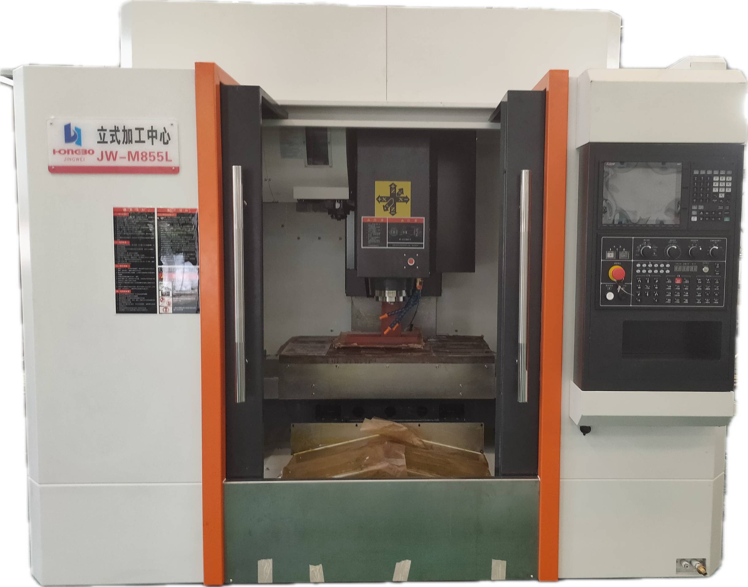
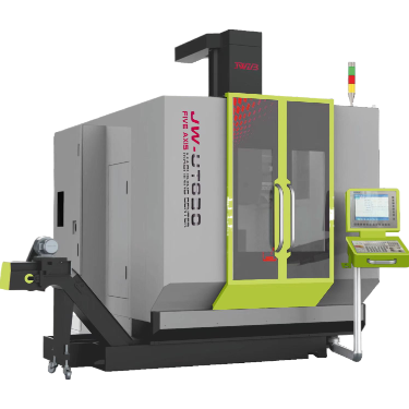
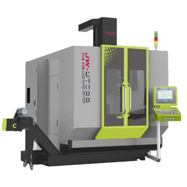
- The JW-U400 is a high-performance five-axis machining center with a portal structure, mainly suitable for parts processing in industries such as 3C digital products, small and medium-sized impellers, and precision mold manufacturing. The machine body has achieved excellent mechanical properties through finite element analysis. It is cast with high-quality cast iron, reinforced with a gantry frame, and all cast iron undergoes annealing treatment, ensuring high stability and minimal deformation.
- Equipped with LL torque motor cradle five-axis (other brands are optional), it is suitable for various metal and non-metal materials. With the SYNTEC control system, it can achieve five-axis linkage processing of high-precision and complex curved surfaces, as well as a four-and-a-half-axis processing method of multi-face processing in one clamping. It has outstanding advantages in processing accuracy and efficiency.
- The three-axis lead screws and guide rails all adopt well-known brands from Germany and other industries. The lead screw with a 16mm lead and pre-tensioning at the tail end ensures processing accuracy (grating is optional), and the high-rigidity guide rail guarantees the service life of the machine.
- 4. Equipped with a 20,000 RPM high-speed milling BBT30 spindle, the spindle adopts high-precision bearings and the optimal shafting layout, featuring high operational accuracy, high stability, as well as great rigidity and load-bearing capacity. A circulating cooling channel is set inside the main shaft. Under the operation of the external water cooler, the heat generated by the rotation of the main shaft is quickly carried away, enabling the main shaft to quickly enter a lower thermal equilibrium state. This ensures the dimensional stability of the processed products and maintains the long service life of the main shaft.
- The tool magazine adopts the 21-tool umbrella servo tool magazine of Beiju. Compared with the conventional tool arm tool magazine, it has the advantages of rapid tool change and precise positioning.
- It is equipped with a standard river Valley integrated automatic oil lubrication system to ensure good lubrication of all moving parts of the machine tool, smooth operation and increase the service life of the lead screw and guide rail. Compared with the traditional thin oil lubrication method, oil lubrication reduces the frequent oiling frequency, provides more thorough lubrication, and keeps the interior of the machine cleaner.
- Equipped with a tool setter, after tool setting, it can automatically set the offset value of the tool to the workpiece coordinate system, thereby automatically establishing the workpiece coordinate system. It is very convenient to set the coordinate values of the workpiece. It not only saves time but also improves efficiency.
- The three axes are equipped with high-quality protective covers, providing excellent protection. The surface of the organ is covered with stainless steel scales to prevent iron filings from cutting the protective cover and increase its service life. The workbench slope is used for chip flushing. The rear row is placed on one side near the door of the base. While concentrating the discharge of iron filings, it provides users with a more humanized space for cleaning the machine body.
- Equipped with two high-power water pumps, the cutting tools and workpieces can be fully cooled during processing, and the water flushing and chip removal are more thorough.
II.Parameters and Configuration
1. Technical parameters
| Project | Name | Parameters | Remarks |
| Processing range | Distance from spindle nose to disk surface(mm) | 55-385 | Disk level |
|
Table Travel |
X-axis Stroke(mm) | 500 | X-axis |
| Y-axis Stroke(mm) | 400 | Y-axial | |
| Vertical stroke(mm) | 330 | Z-axis | |
|
Cradle |
drive mode | Torque motor direct drive | |
| The A-axis swing angle(deg) | ±130° | Tilt shaft | |
| The C-axis swing angle(deg) | n×360° | Rotation axis | |
| Disk diameter(mm) | Φ260 | ||
| Maximum workpiece diameter(mm) | Φ400 | ||
| T groove(n/mm) | 4/12H7 | ||
| Maximum height of artifacts(mm) | 285 | A+90 degrees | |
| Workpiece load capacity(kg) | ≤60 | ||
| A-axis torque (rated / max. N.m) | 120/240 | DD direct drive | |
| C axis torque(Rated / max. N.m) | 45/135 | DD direct drive | |
|
principal axis |
Taper hole model | BT30 | |
| maximum speed(rpm) | 36000 | ||
| driving mode | Direct connection | ||
| power rating(kW) | 5.5 | ||
| rating torque(N.m) | 28 | S1 | |
| numerical control system | System brand | Syntec | |
| Operate the screen | 10-inch high-definition LCD screen | ||
|
drive
|
X/Y/Z ball screw(Diameter guide mm) | 2812 | |
| X/Y/Z Axis guide rail | 30#/30#/35# | ||
| X/Y/Z Fast moving speed(m/min) | 30/30/30 | ||
| A / C axis fast speed(m/min) | 100/200 |
| X/Y/Z power of motor (kW) | 1.8/1.8/2.9 | Z-axis lock | |
|
tool magazine
|
Knife library capacity (handle) | 21 | |
| Change change time (knife to sec) | 2 | ||
| Maximum tool length (mm) | 250 | ||
| Maximum tool weight(kg) | 8 | ||
| Maximum knife plate adjacent knife diameter(mm) | 70/120 | ||
| Machine tool accuracy | X/Y/Z positioning accuracy(mm) | 0.005 | |
| X/Y/Z Repeat positioning accuracy(mm) | 0.003 | ||
| A/C positioning accuracy(sec) | ±8 | ||
| A/C Repeat positioning accuracy(sec) | ±6 | ||
|
Machine tool size
|
Machine tool size | About 1800*2400*2450 | Long * wide*high |
| Machine tool weight(t) | About 3.8 | ||
| other | numerical control system | Syntec 220MA-5 | |
| Total electrical capacity Kw | 20 | ||
| Pressure required MPa | 0.6~0.7 | ||
| The gas flow required(m³/min) | 0.15 | ||
| power requirement | Three-phase380V/50Hz |
Note: This parameter table is subject to technical change without notice
2.Control system configuration
| Serial number | Name | Model specification | Quantity | Remarks |
| 1 | Controller unit | Syntec | 1 | Taiwan Syntec |
| 2 | MCP unit | 3012 Word keyboard | 1 | Taiwan Syntec |
| 3 | Panel | 3030 Operation panel | 1 | Taiwan Syntec |
| 4 | Four-in-one
servo driver |
SMA-35/35/35-100-XL | 2 | Taiwan Syntec |
| 6 | X-axis servo motor | AM11-40-F3 | 1 | 2.4Kw |
| 7 | Y-axis servo motor | AM11-40-F3 | 1 | 2.4Kw |
| 8 | Z-axis servo motor | AM18-30B-F4 | 1 | 3.9Kw |
| 9 | A-axis direct drive driver | SVH-020-B | 1 | Taiwan Syntec |
| 10 | C-axis direct drive driver | SVH-020-B | 1 | Taiwan Syntec |
3. Key spare parts brand configuration table
| Project | Name | Brand | Origin | Remarks |
| 1 | Control system | Syntec | Taiwan | 220MA-5 |
| 2 | Spindle | Ruiying | Taiwan | BT30 |
| 3 | Tool magazine | Bei Ju | Taiwan | 20T servo
tool magazine |
| 4 | Lead screw | THK | Japan | 3216 |
| 5 | Guide rail | Rexroth | Germany | 30/30/35 |
| 6 | Three-axis motor | Syntec | Taiwan | |
| 7 | Three-axis drive | Syntec | Taiwan | |
| 8 | Direct drive driver | Syntec | Taiwan | |
| 9 | Spindle driver | Syntec | Taiwan | |
| 10 | Main electrical components | Schneider | China-french JV | |
| 11 | Ball screw bearing | FAG | Germany | |
| 12 | Precision locking nut | Yingxi | Taiwan | |
| 13 | Lubrication system | River Valley | Taiwan | 1.5L |
| 14 | Pneumatic system | Yadek | Taiwan | |
| 15 | Oil cooler | Red | Guangdong | |
| 16 | Heat exchanger | Red | Guangdong | |
| 17 | Water pump | Jiahe | Guangdong |
Note: Our company reserves the right to change brands of the same quality
4.Standard configuration table
| Project | Name | Quantity(Unit:set) | Remarks |
| 1 | Syntec CNC system | 1 | 220MA-5 |
| 2 | Full Enclosure | 1 | |
| 3 | Guideway Covers | 1 | includes 5-axis protection |
| 4 | Automatic lubrication system | 1 | |
| 5 | Workpiece cooling system | 1 | |
| 6 | Spindle cooling system | 1 | |
| 7 | Handheld
operation unit |
1 | |
| 8 | Twenty-one umbrella-type servo tool magazines | 1 | |
| 9 | Three-color alarm light | 1 | |
| 10 | Lighting device | 1 | |
| 11 | Air gun | 1 | |
| 12 | Anchor assembly | 1 | Five floor MATS,
screws and nuts |
5. File
| Project | Name | Quantity | Remarks |
| 1 | Packing list | 1 | Paper Documents |
| 2 | Certificate | 1 | Paper Documents |
III. Environmental Requirements and Other auxiliary equipment
| Project | Item | Requirement |
| 1 | Ambient
temperature |
The working environment temperature should range from +5℃ to +40℃. If the temperature exceeds the ambient range, air conditioning should be added to ensure processing accuracy |
| 2 | Environmental humidity | Relative humidity ≤80% |
| 3 | Lightning protection | The installation environment of the equipment should have lightning protection measures. If there are no lightning protection measures, lightning strike accidents may occur during lightning strike weather |
|
4 |
Surrounding environment |
1.The machine tool must not be installed in the area directly exposed to the sun.
2.Keep away from oil stains, dust and corrosive gases; 3.Stay away from equipment with significant vibration, such as air compressor rooms and press workshops, etc. 4.There should be at least a distance of 1 meter from other equipment (or walls). 5. Stay away from electrical interference equipment, such as electric welding machines, etc. |
| 5 | Ground
Requirements |
The ground should be stable and solid. Within the effective installation range of any single machine tool, the height difference should not exceed 10mm. |
Iv. Installation and Acceptance
1.After the machine tool arrives at the site of Party A, Party A is responsible for the foundation, unloading, hoisting, unpacking and positioning of the machine tool, etc.
2.After the machine tool is delivered to the site of Party A, Party A shall complete the final acceptance within 10 days. Failed to be present due to reasons of Party A.If the final acceptance is completed within 10 days, it will be regarded as the final acceptance of Party A being qualified, and the machine tool will automatically enter the warranty period.
3.Acceptance content: The acceptance shall be carried out in accordance with the precision specified in the certificate of conformity provided by Party B. Items that require the use of dedicated testing instruments and inspection tools for the manufacturing plant shall not be subject to repeated testing.
4.Auxiliary materials for machine tools such as coolant, cooling oil, cutting fluid, guide rail oil and lubricating grease, etc. shall be purchased and provided by Party A itself.
v.Others
1.Matters not covered in this agreement shall be resolved through friendly consultation between the two parties.
2.This agreement, as an annex to the contract, shall come into effect simultaneously with the sales contract upon signature or seal by both Party A and Party B.
3.This agreement is made in duplicate, with each party (Party A and Party B) holding one copy. Both copies have the same legal effect.